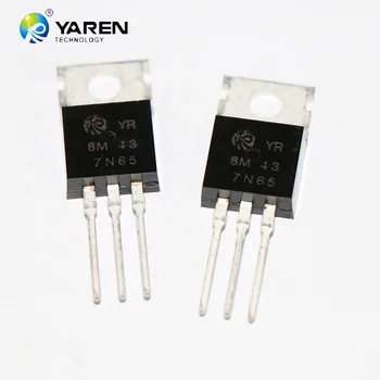
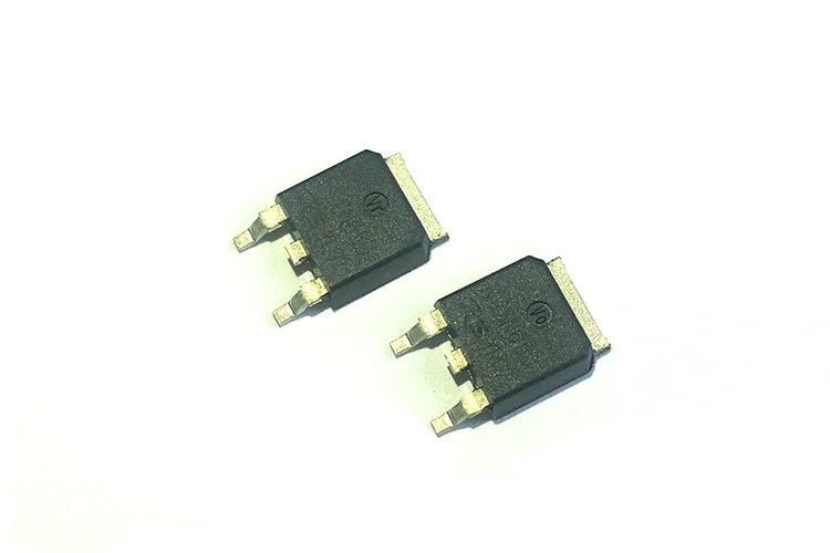
7n65 Mosfet


7 Amps, 650 Volts. N-CHANNEL POWER MOSFET. The UTC 7N65 is a high voltage MOSFET and is designed to. Have better characteristics, such as fast switching time, low gate. Charge, low on-state resistance and have a high rugged avalanche.

Transistor mosfet 7n65

电子元件查询网查出的svd7n65af资料有svd7n65af pdf和svd7n65af datasheet,有多个芯片厂家的清晰datasheet资料,方便工程师快速阅读。. UNISONIC TECHNOLOGIES CO., LTD 7N65 Power MOSFET 7.4A, 650V N-CHANNEL POWER MOSFET DESCRIPTION The UTC 7N65 is a high voltage power MOSFET and is designed to have better characteristics, such as fast switching time, low gate charge, low on-state resistance and have a high rugged avalanche characteristics.

7n65

Fairchild Semiconductor Electronic Components Datasheet

FQP7N65C

No Preview Available !

FQP7N65C/FQPF7N65C
QFET®
These N-Channel enhancement mode power field effect
transistors are produced using Fairchild’s proprietary,
This advanced technology has been especially tailored to
minimize on-state resistance, provide superior switching
performance, and withstand high energy pulse in the
avalanche and commutation mode. These devices are well
suited for high efficiency switched mode power supplies,
active power factor correction, electronic lamp ballasts
Features
• Low gate charge ( typical 28 nC)
• Fast switching
• Improved dv/dt capability
!
TO-220
GD S
FQPF Series
!
Absolute Maximum Ratings TC = 25°C unless otherwise noted
Parameter
Drain-Source Voltage
- Continuous (TC = 100°C)
(Note 1)
Gate-Source Voltage
(Note 2)
(Note 1)
(Note 1)
Peak Diode Recovery dv/dt
PD Power Dissipation (TC = 25°C)
TJ, TSTG
TL
1/8' from case for 5 seconds
* Drain current limited by maximum junction temperature.
650
4.2 4.2 *
± 30
7
4.5
1.28 0.42
300
V
A
V
A
V/ns
W/°C
°C
Symbol
RθCS
Parameter
Thermal Resistance, Case-to-Sink Typ.
FQP7N65C
0.5
FQPF7N65C
--
Units
°C/W
©2004 Fairchild Semiconductor Corporation
Datasheet pdf - http://www.DataSheet4U.net/

Persamaan Mosfet 7n65

7n65 MosfetPengganti mosfet 7n657n65 Mosfet

Pengganti Mosfet 7n65

Fairchild Semiconductor Electronic Components Datasheet

FQP7N65C

No Preview Available !

Electrical Characteristics
Parameter
Test Conditions
Off Characteristics
BVDSS
Drain-Source Breakdown Voltage
Coefficient
Zero Gate Voltage Drain Current
IGSSR
Gate-Body Leakage Current, Reverse
ID = 250 µA, Referenced to 25°C
VDS = 520 V, TC = 125°C
VGS = -30 V, VDS = 0 V
--
--
--
0.8
--
--
--
10
-100
V/°C
µA
nA
VGS(th) Gate Threshold Voltage
Static Drain-Source
gFS Forward Transconductance
VGS = 10 V, ID = 3.5 A
(Note 4)
--
--
8
1.4
V
S
Ciss Input Capacitance
Output Capacitance
VDS = 25 V, VGS = 0 V,
-- 955 1245 pF
pF
Switching Characteristics
Turn-On Delay Time
td(off)
tf Turn-Off Fall Time
Qgs Gate-Source Charge
VDD = 325 V, ID = 7A,
VDS = 520 V, ID = 7A,
(Note 4, 5)
--
--
--
--
50 110
55 120
4.5 --
ns
ns
nC
nC
Drain-Source Diode Characteristics and Maximum Ratings
IS Maximum Continuous Drain-Source Diode Forward Current
7
ISM Maximum Pulsed Drain-Source Diode Forward Current
VSD Drain-Source Diode Forward Voltage VGS = 0 V, IS = 7A
trr Reverse Recovery Time
VGS = 0 V, IS = 7A,
(Note 4)
--
3.3
--
1. Repetitive Rating : Pulse width limited by maximum junction temperature
2. L = 8mH, IAS = 7A, VDD = 50V, RG = 25 Ω, Starting TJ = 25°C
3. ISD 7A, di/dt 200A/µs, VDD BVDSS, Starting TJ = 25°C
4. Pulse Test : Pulse width 300µs, Duty cycle 2%
5. Essentially independent of operating temperature
A
ns
©2004 Fairchild Semiconductor Corporation
Datasheet pdf - http://www.DataSheet4U.net/

Transistor Mosfet 7n65